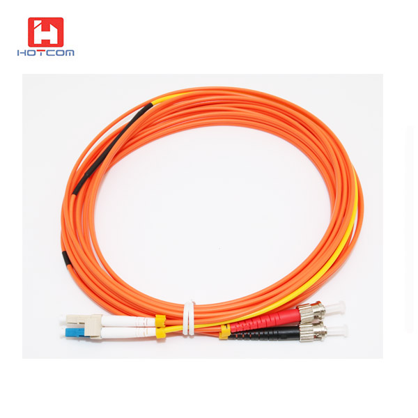
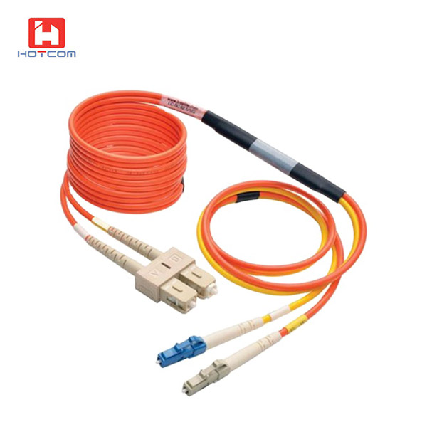
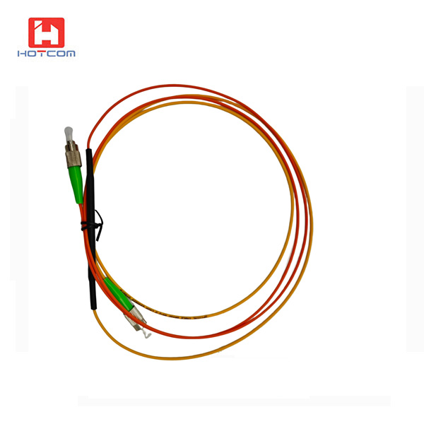
鸿腾光电提供62.5/125和50/125的标准和定制模式转换跳线(MCP),可用于在1300nm窗口中传输的1000BASE-LX/LH和10GBASE-LRM光模块,并应用于多模设备。模式转换光纤跳线在光纤通信系统中主要用于光设备之间或光网络与光设备之间需要进行模场转变的场合,经过模式转换后再经过功率放大器等设备进行调整后,得到需要的光纤模场信号。模场转换跳线主要是单模(SM:9/125um)与多模(MM:50/125um或62.5/125um)之间的转换并制作成跳线的形式。
技术规格
|
连接头
|
ST、SC、FC、LC
|
|
光缆线径
|
2.0 / 3.0mm
|
|
插入损耗
|
光源方向
|
测试波长
|
数据
|
|
A→B
|
850nm、1300nm
|
≤0.20dB
|
|
B→A
|
850nm、1300nm
|
≤0.20dB
|
|
C→D
|
850nm、1300nm
|
≤15.0dB(50/125),≤18.0dB(62.5/125)
|
|
C→D
|
1310nm、1550nm
|
≤2.1dB(50/125),≤2.6dB(62.5/125)
|
|
D→C
|
850nm、1300nm
|
≤0.20dB
|
|
回波损耗
|
单模/UPC≥50dB,APC≥60dB;多模/UPC≥20dB
|
|
端面几何尺寸
|
曲率半径 :10-25mm(PC/UPC) ,5-12mm(APC)
顶点偏移 : 0-50um
光纤凹陷 : ±100 nm
角度:8±2°(APC)
|
|
重复性
|
插拔1000次典型变化值≤0.20dB
|
|
互换性
|
≤0.20dB
|
|
工作温度
|
-20 ~ +70℃
|
|
存储温度
|
-40 ~ +85℃
|
产品结构:

订货信息:
HT-MCP-XX-YY-OM1-SX-2M: 单芯单多模跳线,XX, YY=连接器类型,SC, FC, ST, LC 可选, OM1=多模62.5UM, OM2=50/125UM, 长度=2米(可按需定制)
HT-MCP-XX-YY-OM1-DX-2M:双芯单多模跳线,XX, YY=连接器类型,SC, FC, ST, LC 可选, OM1=多模62.5UM, OM2=50/125UM, 长度=2米(可按需定制)
光有源设备中光链路互连
光纤数据传送、需模式转换的场所
骨干收发网、局域网(LAN)、城域网(MAN)
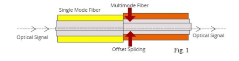
How the Mode Conditioning Cable Works:
The need for this conditioning fiber optic patch cord is due to the single-mode launch nature of the-LX or long-wave(1300nm) transceiver modules used for Gigabit Ethernet.
Launching a single-mode laser into the center of a multimode fiber can cause multiple signals to be generated that confuse the receiver at the other end of the fiber.
In that case, a mode conditioning patch cord eliminates these multiple signals by allowing the single-mode launch to be offset away from the center of a multimode fiber.
This offset point creates a launch that is similar to typical multimode LED launches. (see diagram below)
How to Install the Mode Conditioning Cable:
If your gigabit LX switch is equipped with SC or LC connectors,please be sure to connect the yellow leg(Singlemode)of the cable to the transmit side,and the orange leg(multimode)to the receive side of the equipment.
It is imperative that this configuration be maintained on both ends.The swap of transmit and receive can only be done at the cable plant side.(see diagram below)