100BASE-T SFP Transceiver Module (Copper, 100m, RJ-45)
The HT201-03T 100BASE-T SFP transceiver supports up to 100m link lengths over a copper connection via a RJ-45 connector. Each SFP transceiver module is individually tested to be used on a series of FS switches, routers, servers, network interface card (NICs) etc. Featuring low Featuring low power consumption, the hot swappable 100BASE SFP transceiver is ideal for Internet Service Provider (ISP) Fast Ethernet communication links, Enterprise LAN & SAN Networks, Data Center LAN & SAN Networks and other optical links.
����������
1. Copper SFP module DESCRIPTION
HT201-03T Copper Small Form Pluggable (SFP) transceivers are based on the SFP Multi Source Agreement (MSA) . They are compatible with the 100base-T copper SFP module standards as specified in IEEE Std 802.3. BDTR-FB-P1RC uses the SFP��s RX_LOS pin for link indication. If you pull up the SFP��s TX_DISABLE pin, the SWITCH IC will be reset.
2. PRODUCT FEATURES
l Support 10base-T / 100base-Tx
l Hot-pluggable SFP footprint
l Compact RJ-45 connector assembly
l RoHS compliant and lead-free
l Single +3.3V power supply
l 10/100base-Tx Fast Ethernet over Cat 5 cable
l Ambient Operating temperature: -40��C to +85��C
3. Cable Length
|
Line Side
|
Cable
|
Reach
|
Host Interface
|
|
10base-T
|
CAT5
|
200m
|
100base-FX
|
|
100base-Tx
|
CAT5
|
100m
|
100base-FX
|
4. SFP to Host Connector Pin Out
|
Pin
|
Symbol
|
Name/Description
|
Ref.
|
|
1
|
VEET
|
Transmitter Ground (Common with Receiver Ground)
|
1
|
|
2
|
TFAULT
|
Transmitter Fault. Not supported.
|
|
|
3
|
TDIS
|
Transmitter Disable. Laser output disabled on high or open.
|
2
|
|
4
|
MOD_DEF(2)
|
Module Definition 2. Data line for Serial ID.
|
3
|
|
5
|
MOD_DEF(1)
|
Module Definition 1. Clock line for Serial ID.
|
3
|
|
6
|
MOD_DEF(0)
|
Module Definition 0. Grounded within the module.
|
3
|
|
7
|
Rate Select
|
No connection required
|
|
|
8
|
LOS
|
High indicates no linked. low indicates linked.
|
4
|
|
9
|
VEER
|
Receiver Ground (Common with Transmitter Ground)
|
1
|
|
10
|
VEER
|
Receiver Ground (Common with Transmitter Ground)
|
1
|
|
11
|
VEER
|
Receiver Ground (Common with Transmitter Ground)
|
1
|
|
12
|
RD-
|
Receiver Inverted DATA out. AC Coupled
|
|
|
13
|
RD+
|
Receiver Non-inverted DATA out. AC Coupled
|
|
|
14
|
VEER
|
Receiver Ground (Common with Transmitter Ground)
|
1
|
|
15
|
VCCR
|
Receiver Power Supply
|
|
|
16
|
VCCT
|
Transmitter Power Supply
|
|
|
17
|
VEET
|
Transmitter Ground (Common with Receiver Ground)
|
1
|
|
18
|
TD+
|
Transmitter Non-Inverted DATA in. AC Coupled.
|
|
|
19
|
TD-
|
Transmitter Inverted DATA in. AC Coupled.
|
|
|
20
|
VEET
|
Transmitter Ground (Common with Receiver Ground)
|
1
|
Notes:
-
Circuit ground is connected to chassis ground
-
PHY disabled on TDIS > 2.0V or open, enabled on TDIS< 0.8V
-
Should be pulled up with 4.7k �C 10k Ohms on host board to a voltage between 2.0 V and 3.6 V. MOD_DEF(0) pulls line low to indicate module is plugged in.
-
LVTTL compatible with a maximum voltage of 2.5V.
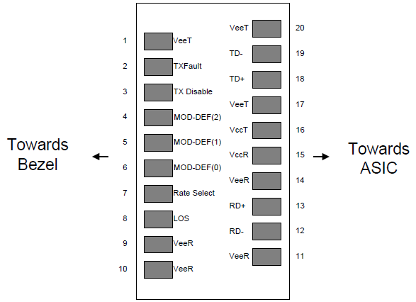
Figure 1. Diagram of host board connector block pin numbers and names
-
+3.3V Volt Electrical Power Interface
The BDTR-FB-P1RC has an input voltage range of 3.3 V +/- 5%. The 4V maximum voltage is not allowed for continuous operation.
|
+3.3 Volt Electrical Power
Interface
|
|
Parameter
|
Symbol
|
Min
|
Typ
|
Max
|
unit
|
Notes/Conditions
|
|
Supply Current
|
Is
|
|
�C
|
300
|
mA
|
1.0W max power over
full range of voltage
and temperature.
See caution note below
|
|
Input Voltage
|
Vcc
|
3.13
|
3.3
|
3.47
|
V
|
Referenced to GND
|
|
Maximum Voltage
|
Vmax
|
|
|
4
|
V
|
|
|
Surge Current
|
Isurge
|
|
TBD
|
|
mA
|
Hot plug above steady state
current. See caution note
below
|
Caution: Power consumption and surge current are higher than the specified values in the SFP MSA
6. Low-Speed Signals
MOD_DEF(1) (SCL) and MOD_DEF(2) (SDA), are open drain CMOS signals (see section VII, ��Serial Communication Protocol��). Both MOD_DEF(1) and MOD_DEF(2) must be pulled up to host_Vcc
|
Low-Speed Signals, Electronic Characteristics
|
|
Parameter
|
Symbol
|
Min
|
Max
|
unit
|
Notes/Conditions
|
|
SFP Output LOW
|
VOL
|
0
|
0.5
|
V
|
4.7k to 10k pull-up to host_Vcc,
measured at host side of connector
|
|
SFP Output HIGH
|
VOH
|
host_Vcc -0.5
|
host_Vcc + 0.3
|
V
|
4.7k to 10k pull-up to host_Vcc,
measured at host side of connector
|
|
SFP Input LOW
|
VIL
|
0
|
0.8
|
V
|
4.7k to 10k pull-up to Vcc,
measured at SFP side of connector
|
|
SFP Input HIGH
|
VIH
|
2
|
Vcc + 0.3
|
V
|
4.7k to 10k pull-up to Vcc,
measured at SFP side of connector
|
7. High-Speed Electrical Interface
All high-speed signals are AC-coupled internally.
|
High-Speed Electrical Interface, Transmission Line-SFP
|
|
Parameter
|
Symbol
|
Min
|
Typ
|
Max
|
unit
|
Notes/Conditions
|
|
Line Frequency
|
fL
|
|
125
|
|
MHz
|
5-level encoding, per
IEEE 802.3
|
|
Tx Output Impedance
|
Zout,TX
|
|
100
|
|
Ohm
|
Differential, for all
frequencies between
1MHz and 125MHz
|
|
Rx Input Impedance
|
Zin,RX
|
|
100
|
|
Ohm
|
Differential, for all
frequencies between
1MHz and 125MHz
|
|
High-Speed Electrical Interface, Host-SFP
|
|
Parameter
|
Symbol
|
Min
|
Typ
|
Max
|
unit
|
Notes/Conditions
|
|
Single ended data input
swing
|
Vinsing
|
250
|
|
1200
|
mV
|
Single ended
|
|
Single ended data output
swing
|
Voutsing
|
350
|
|
800
|
mV
|
Single ended
|
|
Rise/Fall Time
|
Tr,Tf
|
|
�C
|
|
psec
|
20%-80%
|
|
Tx Input Impedance
|
Zin
|
|
50
|
|
Ohm
|
Single ended
|
|
Rx Output Impedance
|
Zout
|
|
50
|
|
Ohm
|
Single ended
|
8. Copper SFP module Specifications
|
General
|
|
Parameter
|
Symbol
|
Min
|
Typ
|
Max
|
unit
|
Notes/Conditions
|
|
Data Rate
|
BR
|
10
|
|
100
|
Mb/sec
|
IEEE 802.3 compatible.
See Notes 1,2 below
|
Notes: 1. Clock tolerance is +/- 50 ppm
9. Environmental Specifications
Automatic crossover detection is enabled. External crossover cable is not required
|
Environmental
Specifications
|
|
Parameter
|
Symbol
|
Min
|
Typ
|
Max
|
unit
|
Notes/Conditions
|
|
Operating Temperature
|
Top
|
-40
|
|
85
|
��C
|
Case temperature
|
|
Storage Temperature
|
Tsto
|
-40
|
|
85
|
��C
|
Ambient temperature
|
-
Serial Communication Protocol
All WINTOP SFPs support the 2-wire serial communication protocol outlined in the SFP MSA. These SFPs use an MCU, can be accessed with address of A0h.
|
Serial Bus Timing, Requirements
|
|
Parameter
|
Symbol
|
Min
|
Typ
|
Max
|
unit
|
Notes/Conditions
|
|
I 2C Clock Rate
|
|
0
|
|
200,000
|
Hz
|
|
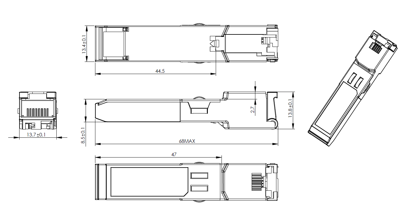
-
Mechanical Specifications (Unit:mm)