SPECIFICATIONS | |||
OUTPUT | |||
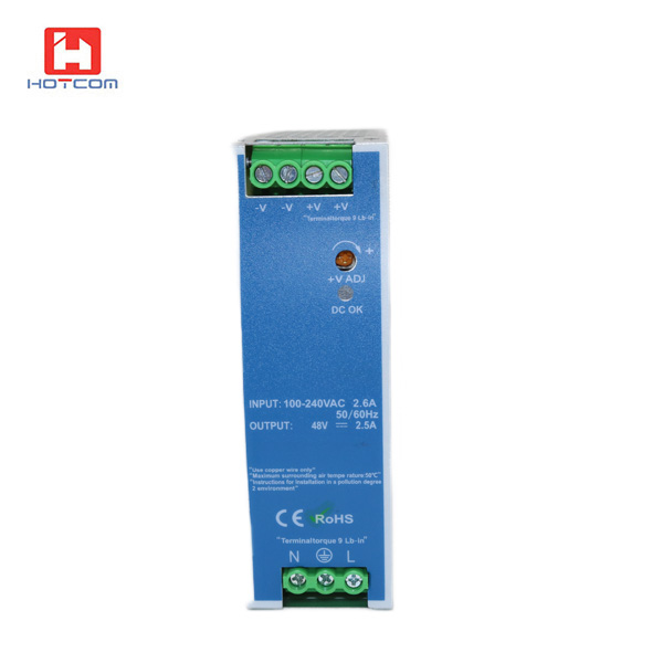
Model | HT-DR-120-12 | HT-DR-120-24 | HT-DR-120-48 |
DC Voltage | 12V | 24V | 48V |
Rated Current | 10A | 5A | 2.5A |
Current Range | 0-10A | 0-5A | 0-2.5A |
Rated Power | 120W | 120W | 120W |
Ripple & Noise | 80mVp-p | 80mVp-p | 100mVp-p |
Voltage Adj. Range | 12-14V | 24-28V | 48-53V |
Voltage Tolerance | ±2% | ±1% | ±1% |
Line regulation | ±0.5% | ±0.5% | ±0.5% |
Load regulation | ±1% | ±1% | ±1% |
Setup, Rise Time | 500ms,70ms/230VAC 500ms,70ms/115VAC at full load | ||
Hold Up Time | 36ms/230VAC 32ms/115VAC at full load | ||
INPUT | |||
Voltage Range | 88~132VAC/176~264VAC selected by switch 47~63Hz; 248~370VDC | ||
AC Current | 2.6A/115VAC 1.6A/230VAC | ||
Efficiency | 80% | 84% | 85% |
Inrush Current | Cold start 20A/115V 40A/230V | ||
Leakage Current | <3.5mA/240VAC | ||
PROTECTION | |||
Over Load | 105%~150% rated output power | ||
Protection type: Constant current limiting, recovers automatically after fault condition is removed | |||
Over Voltage | 15-16.5V | 29-33V | 58-65V |
Protection type: Shut down o/p voltage, re-power on to recover | |||
Over Temp. | 85℃±5℃(TSW1) | 90℃±5℃(TSW1) | 90℃±5℃(TSW1) |
Protection type: Shut down o/p voltage, recovers automatically after temperature goes down | |||
ENVIRONMENT | |||
Working Temp., Humidity | -10℃~+60℃; 20%~90% RH non-condensing | ||
Storage Temp., Humidity | -20℃~+85℃; 10%~95%RH | ||
Vibration | 10~500Hz, 2G 10min./1cycle, period for 60min, each along X, Y, Z axes | ||
SAFETY | |||
Withstand Voltage | I/P-O/P: 3KVAC I/P-FG: 1.5KVAC O/P-FG: 0.5KVAC | ||
Isolation Resistance | I/P-O/P, I/P-FG, O/P-FG: 100M Ohms / 500VDC/25℃/70%RH | ||
STANDARD | |||
Safety Standard | Design refer to UL508,UL60950-1,TUV EN60950-1 | ||
EMC Standard | Design refer to EN55011,EN55022,EN61000-3-2,-3,EN61000-4-2,3,4,5,6,8,11,EN55024,EN61000-6-2(EN50082-2), heavy industry level, criteria A | ||
OTHERS | |||
Dimension | 65.5*125.2*100mm(L*W*H) | ||
Weight | 0.79Kg | ||
Packing | 20pcs/carton/16.5kg/1.29CUFT |
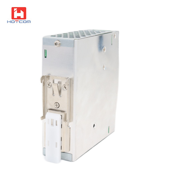
12V 10A, 24V 5A, 48V 2.5A Din-Rail Industrial Switching Power Adaptor
Correct usage of Din-Rail Industrial Switching Power Adaptor
1. The specification of AC voltage used in Din-Rail Industrial Switching Power Adaptor is 110VAC/ 220VAC/ 380VAC power supply. Before power on, check whether the connected voltage is consistent with the input voltage of power supply.
2. Before the first power on, do not connect the load. First, check whether the output voltage of the power supply is consistent with the power supply of the connected equipment, so as not to damage the connected equipment.
3. The ground wire should be connected well before the power supply is used. The ground wire of this type of power supply should be marked in the figure.
4. The power supply should be placed in the center with good ventilation.
5. The output current of Din-Rail Industrial Switching Power Adaptor is definitely fixed; According to the rated standard current of the equipment supplied by the guide power supply or the multimeter to measure the uniform current value is sure. In the case of high ambient temperature, poor air activity and rational load, 20-30% extra current allowance should be prepared.
6.The input power of Din-Rail Industrial Switching Power Adaptor is determined: the input power of guide power supply depends on the rated marked power of the supplied equipment. If the rated power of the supplied equipment is unknown, the product value of the rated current and voltage of the supplied equipment can be used to obtain (current X voltage = power). When the user selects the power supply, it should be greater than 15-30% of the practical power and peak power.
7. Din-Rail Industrial Switching Power Adaptor output DC number is determined: guide power supply has a maximum of four conventional output. (S-single group, D-double group, T-three group, q-four group) according to the equipment provided for confirmation.
8. Din-Rail Industrial Switching Power Adaptor has over/under voltage, over current, overheat maintenance and fan cooling maintenance functions. Please stop the selection according to the practical application condition, in order to strengthen the stability and reliability of the system engineering.